This is a french translation of Roger Quartermain and the lost script of the Heisei era originally published on ROMHack forum(a french forum about videogame fan translations).
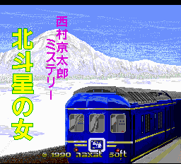
Roger est heureux. Il a récemment fait l’acquisition à vil prix d’un jeu PC-Engine CDROM, “Nishimura Kyotaro Mystery.: Hokutosei No Onna”. Selon toute vraisemblance, il s’agirait d’un jeu d’enquête policière comme J.B. Harold Murder Club, Jake Hunter, Ace Attorney, Le Manoir de Mortevielle ou encore Maupiti Island.
Il fut publié à l’aube de l’année 1990 par Naxat (maintenant Kaga Create).
Alors qu’il glisse délicatement le disque dans sa bonne vieille DUO, il se rappelle que certains jeux offrent la possibilité de changer la langue. Par exemple, la version japonaise de J.B Harold Murder Club peut être joué en anglais. Malheureusement une telle option est introuvable dans Hokutosei No Onna… Qu’à cela ne tienne! Roger Quatermain attrape ses bottes, son chapeau et plonge vaillamment dans les entrailles sombres et fumeuses du jeu.
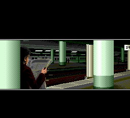
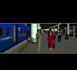
L’introduction montre un pauvre quidam se faire poignarder, deux jeunes femmes insouciantes se rendant à une gare et un personnage louche en train de les espionner.
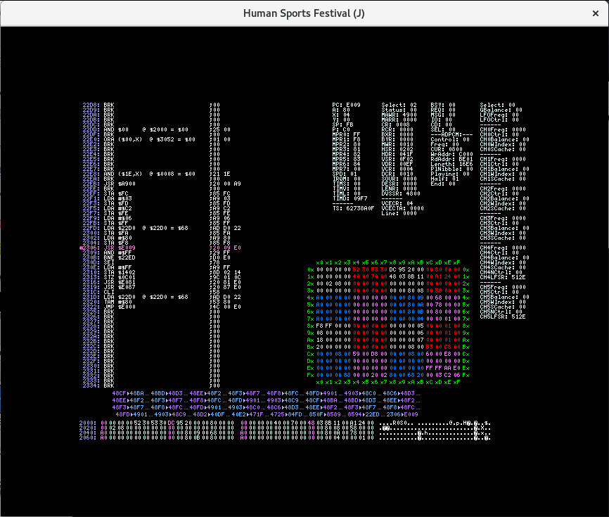
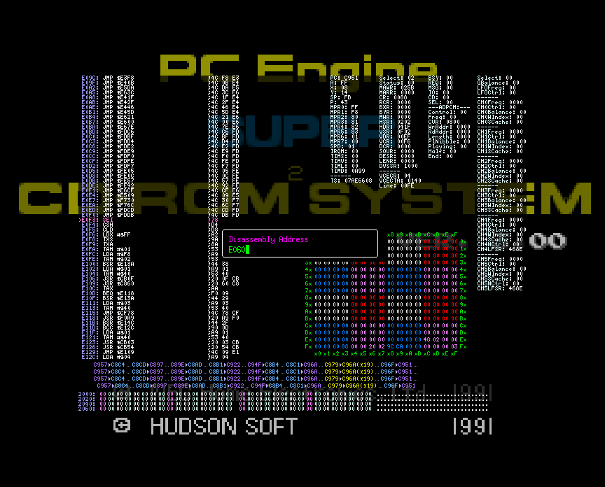
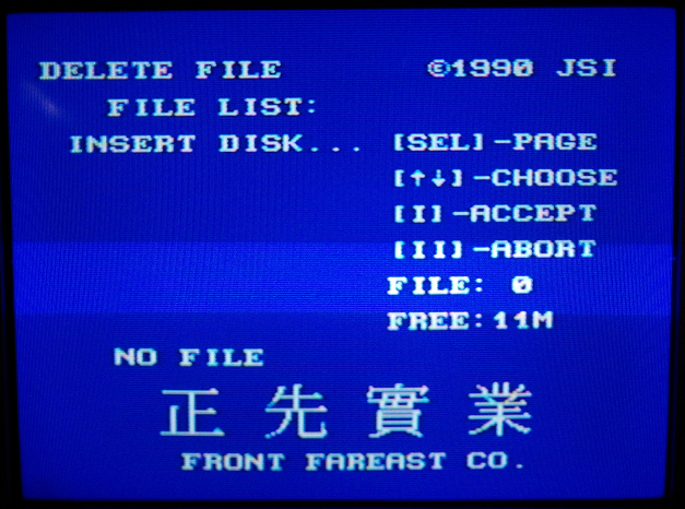
S’agissant d’un jeu CDRom, ce dernier utilise la fonction du BIOS pour afficher le texte. Roger saisit ses vieilles notes et les parcourt frénétiquement en quête d’informations sur une quelconque routine d’affichage de texte. Et la voici! ex_fnt à l’adresse $e060. Il dégaine alors son émulateur favori et positionne un point d’arrêt à l’adresse indiquée.
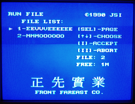
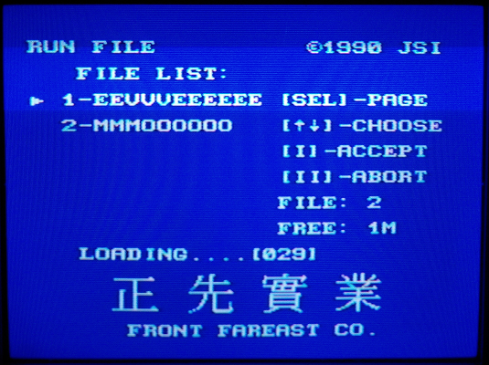
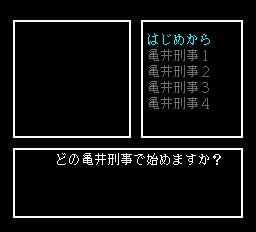
Le point d’arrêt est atteint après l’introduction sur ce qui semble être l’écran de sélection des sauvegardes à charger.
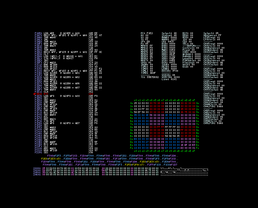
Contrairement à ce qu’il pouvait laisser entendre Roger n’est pas intéressé par ex_fnt mais par le code appelant cette routine. Pour ce faire il place des points d’arrêts sur toutes les instructions rts d’ex_fnt. Une brève pression sur la touche R l’amène sur $f1e2. Une autre pression sur la touche S l’envoie sur l’appelant.
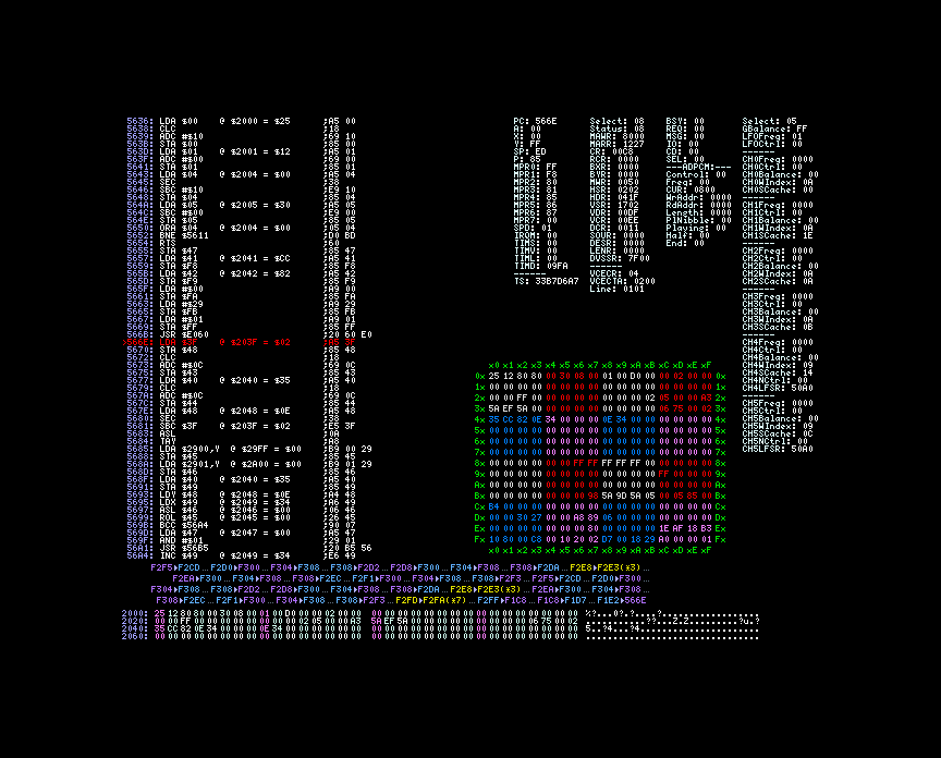
Il se retrouve donc à $566b.
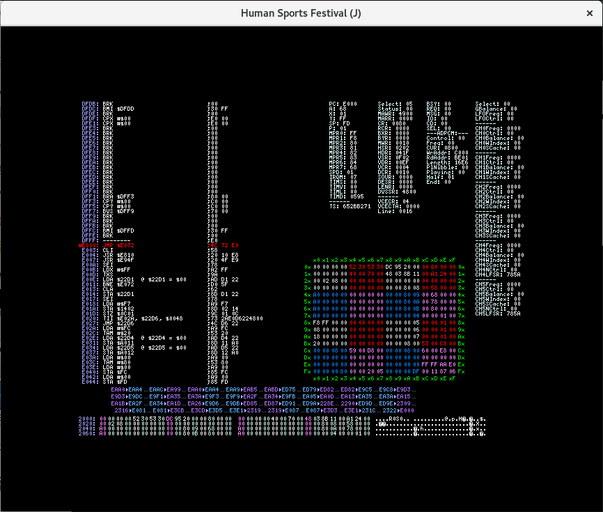
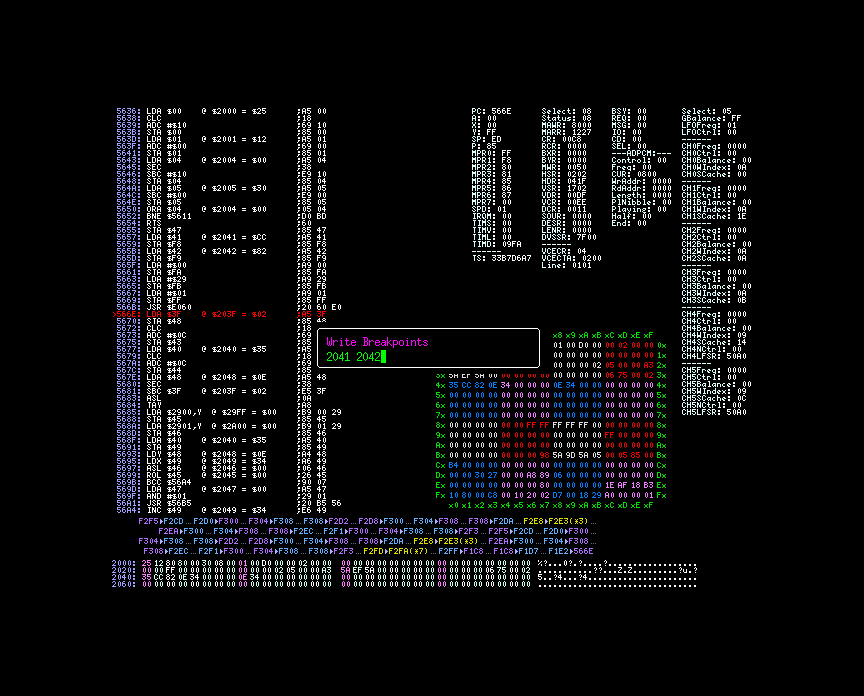
D’après les notes, le symbole shift-jis est chargé depuis $41, $42 vers $f8 et $f9. La logique lui dicte donc de placer un point d’arrêt en écriture sur les adresses $41 et $42.
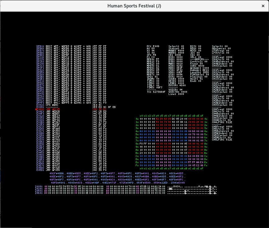
Le point d’arrêt est levé en $5b20. Le code est somme toute assez simple.
5b1c: ldy #$00
      lda ($3c), Y
5b20: sta $41
      iny
      lda ($3c), Y
      iny
      sta $42
L’étape suivante consiste à chercher où le pointeur $3c est initialisé. Roger place donc un autre point d’arrêt $3c et $3d.
5a18: lda #$90
      bra $5a22
      lda #$40
      bra $5a22
      lda #$80
5a22: sta $c0
5a24: sty $3d
      cpy #$00
      beq $5a2f
      stx $3c
      smb5 $c0
      rts
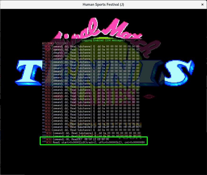
Malheureusement le code appelant est tout sauf trivial. Par contre la bonne nouvelle est que le texte n’est pas compressé. En notant attentivement les valeurs stockées en $41 et $42, Roger réussit à extraire la chaîne:
40 81 40 81 40 81 C7 82 CC 82 54 8B E4 88 59 8C 96 8E C5 82 6E 8E DF 82 DC 82 B7 82 A9 82 48 81 0D 00 FF 00
Le boutisme doit être inversé. Heureusement il a sous le coude un script Perl fort utile, swap_endian.pl. Les 4 derniers caractères ressemblent à des codes de contrôle. Sa grande et longue expérience lui permet de déduire que 00 0D doit symboliser un saut de ligne et 00 FF la fin du texte. Voici la chaîne décodée.
どの亀井刑事で始めますか?
Mais tout cela ne lui dit pas où le pointeur
$3c est initialisé. Roger sait que sur CDRom le code est d’abord transféré en RAM avant d’être exécuté. Cela signifie aussi que le code peut être auto-modifiable. Et manque de chance, c’est le cas ici. Roger doit encore mettre un point d’arrêt à l’emplacement où le saut est effectué et suivre le fil d’exécution jusqu’à atteindre l’emplacement où le pointeur est initialisé. Plusieurs heures passent et il échoue finalement en
$724d
724d: ldx #$fc
      ldy #$74
      jmp $5a18
Il redémarre le jeu en ne laissant qu’un point d’arrêt sur $41 et $42. Comme prévu il se retrouve là où il a découvert la première chaine. Il décide donc de continuer son chemin et se retrouve en $acb4.
acae: lda $4f
      asl A
      tay
      lda ($50), Y
acb4: sta $41
      iny
      lda ($50), Y
      beq $acd8
      sta $42
      lda $2922
      sta $3f
      lda $2923
      sta $40
      lda #$01
      jsr $5655
Le pointeur $50 est initialisé en $ac92.
ac8a: tay
      lda $312a, Y
      asl
ac8e: tay
ac90: lda ($9f), Y
      sta $50
      iny
      lda ($9f), Y
      sta $51
Ainsi donc le pointeur est initialisé à partir d’une table. Ses valeurs sont
Par chance les indexes pour ces pointeurs sont 2,3,4,5,6. Roger cherche dans l’iso la chaîne b1 b6 bd b6 cb b6 d9 b6 e7 b6. Il la trouve à l’offset $11f49. L’endroit semble baigner dans une soupe de pointeurs. Quelques octets plus loin il reconnait du texte en shit-jis. Il commence en $11f53. La “soupe” doit donc contenir des valeurs ressemblant à $53Xf. Il remonte et trouve $53af à $11d45. Tadam, il a sa première table et son premier bloc de texte. Comme tout les pointeurs sont en ordre croissant, Roger en conclue que la liste contenant les noms des options est stockée de $11f53 à $126f4. Il remarque d’autres symboles shift-jis à la suite. Ils vont de $126f5 à $132f5.
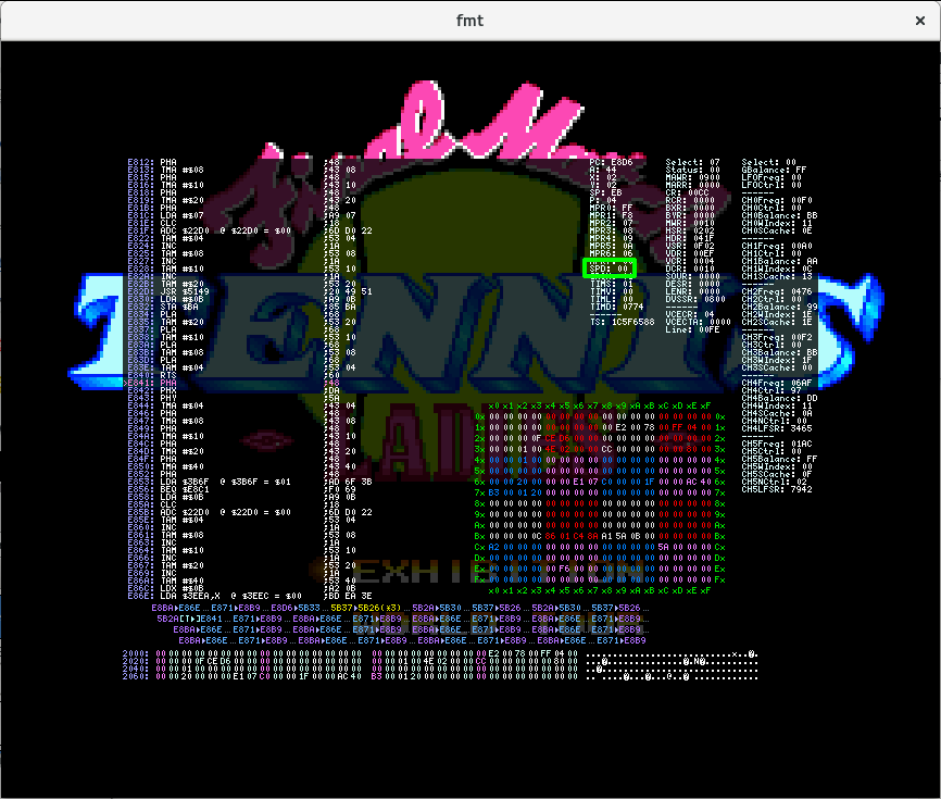
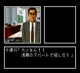
Une fois les options affichées, Il passe sur un autre écran où un vieux briscard de la crim’ lui taille le bout de gras.
Une fois encore il met un point d’arrêt sur $41 et $42. Mais à cet instant il se rappelle de $5a18. Cela commence par:
5a18: lda #$90
      bra $5a22
5a1c: lda #$40
      bra $5a22
5a20: lda #$80
5a22: sta $c0
Il peut donc y arriver depuis $5a18, $5a1c ou $5a20. Cela lui donne 3 points d’arrêt. $5a20 est le grand gagnant et comme il s’en doutait il y arrive par un bout de code auto-généré ($59ab). Une longue et pénible route se prépare à l’horizon. Et pénible elle est. Néanmoins, Il découvre que $5a20 est atteint depuis $6c5e.
6c5e: ldy $a5
      lda ($a8), Y
      sta $00
      iny
      lda ($a8), Y
      sta $01
      iny
      sty $a5
      and $00
      cmp #$ff
      beq $6c79
      ldx $00
      ldy $01
      jmp $5a20
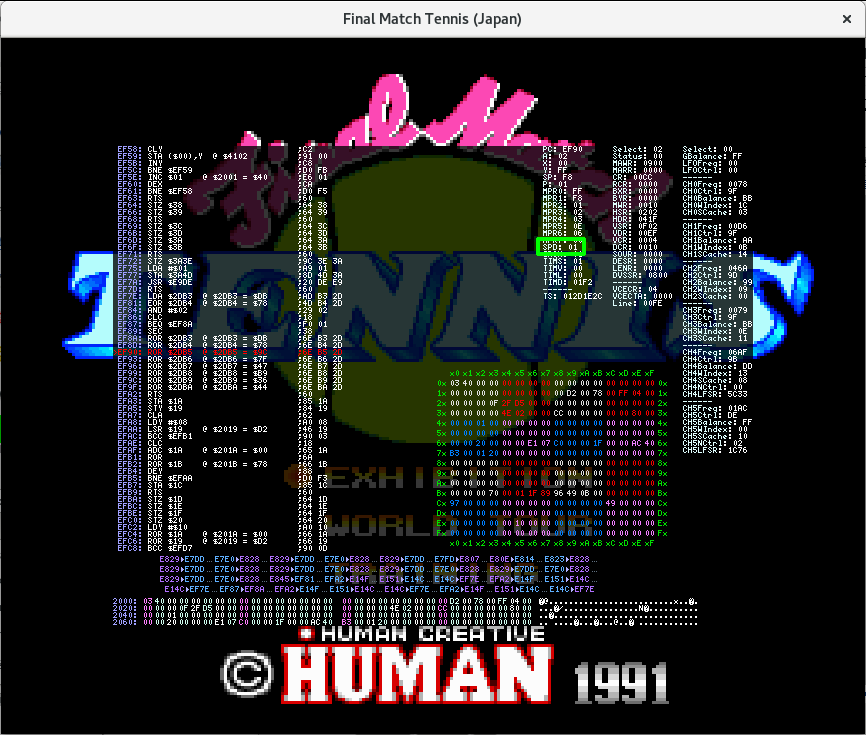
La première phrase du vieux briscard se trouve en $89c9 ($1339c9 dans l’iso). Cette adresse provient d’une table pointée par $a8. Lui même initialisé en $707e.
707e: lda #$00
      sta $00
      lda #$80
      sta $01
      lda ($00), Y
      sta $a8
      iny
      lda ($00), Y
      sta $a9
      stz $a5
      stz $a6
      lda #$03
      jmp $619c
Le pointeur est stocké en $13308c. Roger est perplexe. Il ne s’agit pas d’une simple table de pointeur. Elle contient d’autres données. Que signifient-elles? Mais il est exténué et il y a Extra Sangsues sur le câble.
Il s’étire, ferme l’émulateur et son portable et se prépare pour 90 minutes de pur puissance.