


Last month I ordered some DataFlash (AT45DB161D) chips from Sparkfun. The AT45DB161D is a flash memory with SPI interface. It’s able to store up to 16Mbits of data.
With the DataFlash library for the Arduino in one hand and a solder iron in the other, I was ready to test the beast. Unfortunately the chip is an 8 pin SOIC. So I had to solder it on a SOIC-to-DIP pcb. Luckily Sparkfun (again) was selling an 8-Pin SOIC to DIP Adapter. With my legendary bad luck, I realized afterward that the SOIC connectors were too small. I had to bend them a little 😐 The soldering was a massacre…
Anyway, after what seemed to be an hour (in fact it was only 5 minutes) I was finally over with the whole mess. I plugged the DataFlash to the breadboard and connected it to the Arduino (important note : it was an old NG revision). I had to make a simple circuit to convert the 5V output from the Arduino to 3.3V. After a bunch of attempts which ended in burning a 3.3V voltage regulator, I run the test program.
And … Nothing happened. I was getting a bunch of 0000 and FFFF. And the result was the same even if the chip wasn’t connected to the Arduino.
To make things short after destroying another DataFlash (I broke the pins) and hazardous code experiments, it appeared that the old revision of the Arduino NG had problems with SPI.
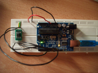
This was a good excuse to buy the new Diecimila Arduino board 🙂 The 9V output was changed for a 3.3V one. I didn’t need my dummy circuit anymore. I also bought a bunch of 8pin SOIC to DIP pcbs from ebay (larger than the Sparkfun ones). The soldering work was easier this time and everything was setup for testing in less than 10 minutes. I uploaded the test program to the board…
Miracle, it worked!
The Arduino DataFlash library was written for the B revision. A lot of things changed from the B to the D revision of the DataFlash. This was a call to write a new library. Unfortunately the on I wrote is specific to the AT45DB161D. It only supports standard page size (528 bytes) and all the security commands are unimplemented. I first need to get extra chips before working on it as these commands can brick the DataFlash.
You can grab the AT45DB161D library for the Arduino here :
You’ll have to put those files in $ARDUINO/lib/targets/libraries/at45db161d ($ARDUINO being the name of you arduino directory).
[Documentation] (Doxygen rules)
Now, I have to find out how to interface the Arduino board to the pcengine. I think I’m up again for a month of painful experiments 🙂
I’d like to change the pin connection assignments on the Arduino, but I’m having a little trouble doing so. I tried reassigning the pin definitions in at45db161d.h to what I needed, but that didn’t work.
Is there something I’m missing?
– Mike
Btw, The work you made public on this chip has been so helpful to me, and I’m sure many, many others.
Thanks a lot!
SPI is implemented in hardware. And unfortunately, you can’t use pins other than pins 10 to 13. But you can reassign the pins for RESET and WP. Or completely ignore them as they are unused at the moment.
Vincent
Hi,
Thank you for nice library.
I’m using your library for my Arduino RSS reader project. I use AT45DB161D flash memory to store Kanji (Japanese) font data. The followings are feedback from my experience;
1) ATD45DB161D::ComparePageToBuffer()
Bit 6 of status register (COMPARE) is set to 0 in case data in the main memory page matches the data in the buffer.
Thus, to ComparePageToBuffer function retrun to 1 on compare success, I modified the code as follows;
/* Wait for the end of the comparaison and get the result */
while(!((status = ReadStatusRegister()) & READY_BUSY))
{}
if ( status & COMPARE )
return 0; /* If (COMPARE bit = 1) then Error */
else
return 1;
2) ATD45DB161D::EndAndWait()
If ATD45DB161D is coexist with other SPI device such as Ethernet Shield, SS (Slave Select) pin should be driven High (SS inactive) after the device access. To ensure SS high, I added the following code;
void ATD45DB161D::EndAndWait()
{
DF_CS_inactive; /* End current operation */
DF_CS_active; /* Some internal operation may occur
* (buffer to page transfer, page erase, etc… ) */
/* Wait for the chip to be ready */
while(!(ReadStatusRegister() & READY_BUSY))
{}
DF_CS_inactive; /* Release SPI Bus */ <== Add this code
}
EndAndWait() is called every time after read/write access to ATD45DB161D like this;
dataflash.ContinuousArrayRead(dfAddress[0], dfAddress[1], 1);
for (i = 0; i < dataLength; i++)
fontBuf[i] = spi_transfer(0xff);
dataflash.EndAndWait();
Thanks for the feedback!
I put the code on github if you want to apply your fixes.
http://github.com/BlockoS/arduino-dataflash
Crap! I tried to apply your fixes using github online edit. And it stripped out half of the code 🙁
I’ll re-commit it tonight. grmbl…
[Edit] Fixed.
The codes is great.
But I found a little bug 🙂
Please check a function named ContinuousArrayRead.
http://www.atmel.com/dyn/resources/prod_documents/doc3500.pdf
AT45DB161D_CONTINUOUS_READ_HIGH_FREQ(Opcode:0x0B) has a additional don’t care byte.
Please add “if (!low) { spi_transfer(0x00); }” to end of the function.
Thanks.
Shin.
Thanks for the report.
I’ll fix it ASAP and update the repo on github.
I am working on an Arduino project that will have two SPI peripherals, DataFlash and an LCD. Clearly, I need to use different chip select pins for the two peripherals, i.e., they can’t both be Arduino pin 10. Finally, I seem to have found a solution using the AT45DB161D library on this website with a minor modification. Pin 10 is dedicated to informing the Arduino SPI subsystem that it is the master, by making pin 10 an output and setting it high. Then I am able to use other available digital pins as the chip select for DataFlash.
If you have any request/problem with this code please don’t hesitate to create an issue on github.
@Shin: I added your correction
@Jerry: I plan to add the possibilty to change slave select, reset and write protect pins.
I am not able to get this library to compile in IDE 1.0.3. Do you have plans to support this? I could really use this for my project!
Yes, that’s on the todo-list.
I created an issue on github [here].
I am having some hardware issues which have prevented me from verifying functionality, but I solved the compilation issues with the latest Arduino IDE by updating the includes at the top of at45db161d.h to:
…
#ifndef AT45DB161D_H
#define AT45DB161D_H
#include “Arduino.h”
extern “C” {
#include
};
#include “at45db161d_commands.h”
…
Hi,
I am using ArduinoIDEv1.0.5. I compiled the code here.
I tried the dataflash code for 45db161D. It is giving me 0xFF always, even when I use SPI lib only. What could be possibly wrong.
The pin config is as follows:
Arduino:m2560:51 : 45db161D:SI
Arduino:m2560:52 : 45db161D:SCK
Arduino:m2560:53 : 45db161D:CS(bar)
Arduino:m2560:50 : 45db161D:S0
Arduino:m2560:3v3:45db161D:6
Arduino:m2560:GND:45db161D:7
Pulled high :45db161D:Reset(bar)
Pulled high :45db161D:WP(bar)
I changed the SS in all the places to 53.
Do I have to change anything else in the code.
Thanks
That’s weird. You only have to change the slave select pin value. I tested it on a seeeduino mega and it worked.