I replaced the Möller ray/triangle intersection test by the one using Plücker coordinates. It’s faster and more robust. The results is looking better (smoother normals). But, the holes didn’t disapear. After some investigations, i discovered that the problem came from point normals (I’m using them as point color). I read the objects from ply2 files which only store points and polygon indexes. Here’s how i’m computing point normals:
v is the mesh vertex list
n is the mest point normal list
foreach triangle t
    t.n = normalize(cross(v[t.p1]-v[t.po],v[t.p2]-v[t.po]))
    n[t.p0] += t.n
    n[t.p1] += t.n
    n[t.p2] += t.n
normalize each n
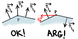
There’s a huge problem here. We are assuming that each polygon (triangle in this case) are ordered so that its normal is pointing away from the object. Unfortunately, this isn’t guaranteed by ply2 format. The following figure illustrates this.

Imagine if t0 and t1 are coplanar. If we are in the worst case, the normals of t0 and t1 are pointing in the opposite directions. As the normal at p is the sum of those two normals, it’ll be equal to the null vector. That explains the black holes. But that’s not all… The normal at the intersection point between the ray and the triangle is interpolated from the point normals of the triangle using barycentric coordinates. One of these 3 normals may be wrong or/and, like the figure, they may be pointing in opposite directions… Arg!
There’s no exact way to determine if a polygon normal is pointing away from the surface. So, unless the file format provides polygon (or in the best case) points normals, i’ll not interpolate point normals.


