


(10/23/2012) WARNING! As Tomaitheous pointed out, there’s a problem with this board! Please refer to comments for more informations.
Yeah a new post!
Some years ago (more like a decade than a year), I bought a Turbo Stick. It’s the standard 2 buttons stick for NEC PC Engine console. Unfortunately the stick makes an awfull squealing nose. Forget 1 life run with this plastic beast. After 5 minutes all I wanted to do was to use it as a soccer ball. According to the Wataru’s PC Engine hardware list, 4 six buttons sticks were released. They are not small and given shipping costs I decided to build one. So I bought a stick and some buttons from Sparkfun. Later a friend gave me a Sanwa stick and buttons.
There are several places on the internet where to find PC Engine pad schematics. The main source are Emanuele Bettidi‘s pad schematics, PCE Wiki, NFG PC engine/TG 16 article. I first built a 2 buttons circuit with no auto fire. But there are a few games that requires a 6 buttons stick (Street Fighter 2 for example). The Avnue Pad 6 comes with auto fire and slow mode. The later is a particular ugly hack. The slow mode is acheived by toggling the pause rapidly. It’s as if you drank too much coffee and go berserk on the RUN button. Here are the guts shots and schematic of an Avenue Pad 6. I spent hours trying to make PCB board in Eagle for the “complete” version (with auto fire and slow mode). I didn’t find a local source for the DTC114Y. A replacement was found on the interweb. It was told that this component can be replaced by a 2N3904 and 2 resistors. This is rather straightforward if you look at the DTC114Y datasheet. Anyway, in the end I didn’t liked the way the board looked. The most logical step was to remove the rapid fire and slow mode (schematic). And by the way, I think I’ll never use slow mode and barely ever used auto-fire.
Here are the current version of the schematic and pcb board:
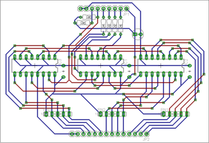

Here’s a 3d view of the nearly version of the board (made with WebGerber)
")
")
I need to add mounting holes in the board. Make some board. And last but not least, build the enclosure!
The 6button pad needs the counter chip (used normally for auto fire) to cycle which set of buttons you are getting. You never know which set you’re gonna receive, so you have to check the directional pad (illegal mode where all four directions are held down, is the new button set). Resetting the pad clocks the counter chip (you read the pad data again after set the reset line).
Arg! You spare me some headaches 🙂
I’ll update the schematic asap (and build a case to test the circuit).
Here’s a dirty fix of the board
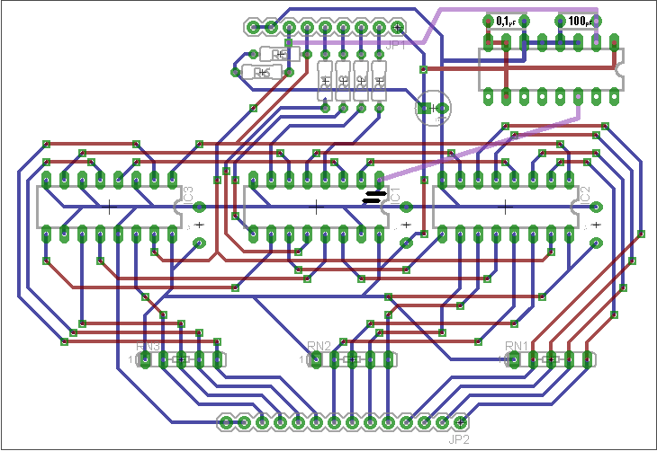
With the updated schematic (img)
Ok the previous fix seems wrong 🙁
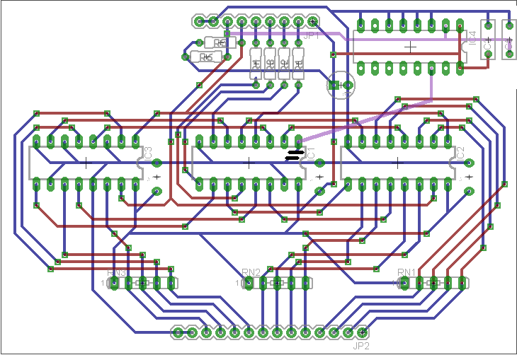
Here’s a new one (I’ll test it asap)