Enter the dragon

I backported the BVH i wrote for CRBN to the little and ugly raytracer test. Even if it’s not the most efficient space partioning method for raytracing, the improvment is quite impressive.

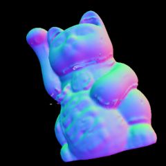
Here’re some results with the Maneki Neko model rendered on a Athlon XP 1.4GHz with 1GB of RAM. The model contains 62385 points and 124677 triangles. The code was compiled only with the -O flag and the target image was 256×256.

BVH:
  • real 0m8.325s
  • user 0m6.461s
  • sys 0m1.505s
  • 174 MB
Without:
  • real 25m57.370s
  • user 24m25.249s
  • sys 0m5.714s
  • 52MB

Nice heh? So i decided to render something a little bit bigger. I chose the dragon hi-res model. It contains 437645 vertices and 871414 triangles. I haven’t tried rendering it without BVH. The 512×512 image took 2minutes to render. Unfortunately, i still have some floating point issues. You can notice holes here and there… I’ll made some tests using Plüecker coordinates as it’s supposed to be more robust.
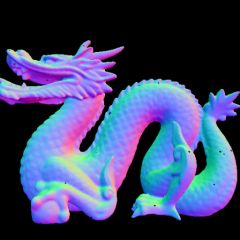
Dragon (small)

8bit archeology

Some years ago, i wrote a very simple and stupid pcengine disassembler in order to check if the rom i produced with wla-dx were correct. Well, time fly and two weeks ago i dig it from the grave. The user can now specify which part of the pcengine rom will be disassembled (code section) and which one are pure data. For this i’m using a csv file. The whole thing is discribed in the README file i quickly wrote tonight 🙂

I started coding it under Linux. As i was in a hurry and lazy, i decided to mmap the rom file. But unfortunately, mmap is not supported/implemented by mingw32. So i had to use my mighty google skills (well koders ones in this case). And the same thing happened with the CSV file parser. I’m using strndup and… i had to recode it :/

Enought ranting! I put everything THERE . The directory contains the complete source code, makefiles for both windows and linux, windows binary and the dev C++ project. As an example, i disassembled Momotaro Desentsu Turbo . I started to document the reset interrupt.

Buddah ray

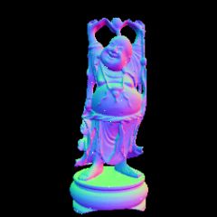
I decided to render a larger model. So i took the happy buddah model from stanford repository. It contains 543652 points and 1087716 triangles. Rendering a 256×256 image took approximatively 2 hours. I really need surface partitioning.

The white dots on the picture represent the ray where a floating point error occured. As the mesh has really small triangles and low coordinates points, i had to replace the zero divider test using boundaries by the standard not equal to zero test. I really hate this floating point issues…

Budda (small)

Raytracing beeps

I quickly wrote some basic polygonal mesh raytracer in order to test some space partitioning algorithm like KD-trees or BIH. I’m actually using the maneki neko from this repository. It’s not really big compared to stanford bunny or happy buddha. As i don’t need any lighting, i decided to use point normal as color. Here’s the result :

Maneki Neko (small)

It took 25 minutes to render this image on my amd64 3500+. The model contains 62385 points and 124677 triangles. Not that much… But it’s brute force raytracing for the moment.
I also discovered that XYZ-RGB is offering free texture materials. Maybe i should use them for the displacement map.

On the 8bit side, the pcengine tracker is going well. The instrument routines may be finished next week. Next step is note/pattern handling.

Triangle Slicing part 2

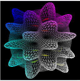
I finally manage to make displacement mapping work. Here are the results for level 8 and 32 subdivisions. Vertex texture fetch seems to be slow on my card (6600 gt).

I need to check if my code is really optimal (well i’m pretty sure it isn’t 🙂 ). But for now, i’m leaving for vacation for 2 weeks!

8 32
Vertex texture fetch 8 Vertex texture fetch 32

Triangle Slicing

Thanks to a java/firefox crash combo, i lost the article i was writing. So here’s a shortened version without all the explanation (i’ll write them later).

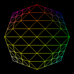
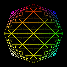
Last week, I came across a paper called “Generic Mesh Refinement on GPU” and decided to implement it. I finished the refinement pattern generation and the use of a vertex shader to display the refined mesh today.
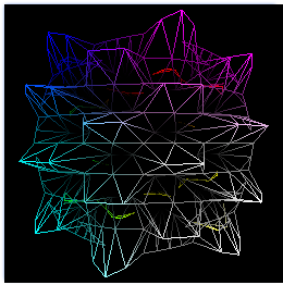
Here are the results:

1 2
Level 1 refinement Level 2 refinement
4 8
Level 4 refinement Level 8 refinement

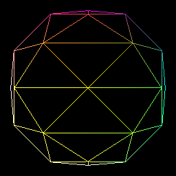
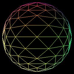
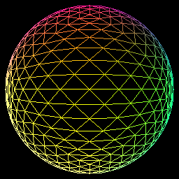
As my main goal is to use this technique for displacement mapping, i modify each point in order to map a sphere:

1 2
Level 1 refinement Level 2 refinement (sphere)
4 8
Level 4 refinement (sphere) Level 8 refinement (sphere)

Attack of the giant snake!

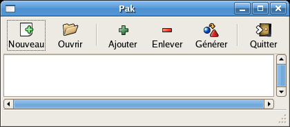
Giant evil snake I’m currently playing with python and gtk. I’m trying to do a homemade package creator. The interface was made with glade, the gtk/gnome interface builder. It’s pretty easy to use. I managed to make a decent interface in about 5 minutes and here’s the result :

Pak interface

Unfortunately, glade can only generate C/C++ code. I searched the web for some way to create python code from glade files and i found something called Kefir.
All i had to do was to call :

python kefir.py myfile.glade

And all the interface code was generated. I now “only” need to code the core of the application. If you want to create pygtk applications under windows, you’ll need to install :

  • Glade and gtk (Gaim users please take care before installing gtk 2.8.x. You won’t be able to connect)
  • PyGtk
  • Python 🙂

I tried Py2exe in order to create an executable out of the python source. I created some basic setup file (mostly ripped from Py2exe documentation and this tutorial). Then i typed :

python setup.py py2exe

Shazam! A directory containing all the required dlls and files was created.

Next step : start coding !