Micro SDisco

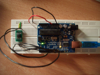
Some months ago, I bought a 4DSystem’s µDRIVE-uSD-G1 (microDRIVE) from Sparkfun. It’s basically a serial module which let you access a microSD memory card (from 512Mb to 2Gig). You may wonder why use an external module as SD cards have a SPI interface? The main reason is … laziness. All file-system operations are performed by the module. So why bother coding fat16 support or whatever? Unfortunately, the current microDRIVE firmware only supports raw access.

Arduino with 4D System\'s uDRIVE-uSD-G1

Anyway, I wrote a small module for the current firmware. It was implemented as a template in order to support various serial implementations. The serial class must provide the following methods :

  • uint8_t read()
  • void print(uint8_t)
  • int available()

It’d have been better if all the serial implementations derived from a same interface. But as I didn’t want to modify the base Arduino code (and as i said earlier, because I’m lazy), I went for the easy/brutal way. And you’d probably never have more than one microDRIVE. At least you want raid 😀

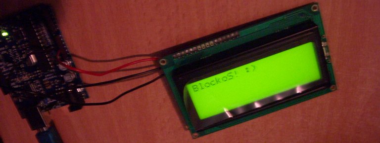
I tested Arduino‘s HardwareSerial and SoftwareSerial, as long as ladyada’s AFSoftSerial. None of the software implementations work 😐 Only soft read is working (hardware tx was used). As software serial is working for the serial LCD, I think the problem might be the autobaud detection during microDRIVE initialization… Or not…

Be careful! There’s a bug in the rev1 firmware. The internal memory address is not incremented to the next sector block after a write operation. It was corrected in the rev2.

MazinSer LCD

Woohoo!

I just got my hands on a 20×4 serial LCD from Sparkfun. It’s basically a standard LCD with a little PIC based serial TTL interface board plugged on it.

10 lines of code and 3 wires later, I had a wonderful “Hello world” displayed on screen. The only problem is that I was using pin 1 (TX) which is shared with the serial USB interface. So when the sketch is uploaded, it’s also sent to the SerLCD. And you end up with garbage on screen. Hopefully, Arduino comes with a soft serial class. It lets you use custom pins for serial communication. The only downside it that it can only run at 4800 baud or 9600 baud.
Next serial fun : 4DSystem’s µDRIVE-uSD-G1.

Here’s the result!

Arduino+SerLCD in action

The mandatory piece of code.

#include <softwareSerial.h>

#define SERLCD_CMD                  0xFE

#define SERLCD_CLEAR                0x01
#define SERLCD_MOVE1_R              0x14
#define SERLCD_MOVE1_L              0x10
#define SERLCD_SCROLL_R             0x1C
#define SERLCD_SCROLL_L             0x18
#define SERLCD_DISP_ON              0x0C
#define SERLCD_DISP_OFF             0x08
#define SERLCD_UNDERLINE_CURSOR_ON  0x0E
#define SERLCD_UNDERLINE_CURSOR_OFF 0x0C
#define SERLCD_BLINKING_CURSOR_ON   0x0D
#define SERLCD_BLINKING_CURSOR_OFF  0x0C
#define SERLCD_SET_CURSOR_POS       0x80
#define SERLCD_CURSOR_OFF           0x0C


#define rxPin 6
#define txPin 7

void setup()
{
  char *str = "BlockoS! :)";
  char *cursor;

  SoftwareSerial mySerial =  SoftwareSerial(rxPin, txPin);

  pinMode(rxPin, INPUT);
  pinMode(txPin, OUTPUT);

  mySerial.begin(9600);

  mySerial.print(SERLCD_CMD, BYTE);
  mySerial.print(SERLCD_CLEAR, BYTE);

  mySerial.print(SERLCD_CMD, BYTE);
  mySerial.print(SERLCD_BLINKING_CURSOR_ON, BYTE);

  for(cursor=str; *cursor!='\0'; ++cursor)
  {
    mySerial.print(*cursor, BYTE);
  }
}

void loop()
{
  /* Nothing */
}

IPS delivery (part 3)

Happy new year!

Just after Christmas, Tomaitheous released Bubblegum Crash patch. Yeepee!

As it’s an IPS patch, I tried to patch the rom with the wonderful ips patcher. Unfortunately, it was unable to patch it. I had a nice “Record offset is out of file bound.” error.
All was IPSProcessRecord function fault. First, I considered the file offset to be out of bound if it was superior or equal to the file size. But if you are appending data to a file, the offset is equal to the file size. Second, I never updated the patched file size. So If we keep appending data to a rom, the bound test will fail.

Anyway! Everything is fixed now. And I was able to successfully apply the patch. So go grab the latest version here:

And as usual, feel free to contact me or leave a comment if you have any request or problem.

IPS delivery (part 2)

Edit: The version listed in this post is buggy. Please consider using version 0.02 [link] or the current development version [link] instead.

Here it is! The gtk version of the ips patcher I wrote earlier.
It’s based on GTK. And I use Glade to create the interface.

I thought I’d have to implement zillions of callbacks but in the all I had to to is attach the IPS structure to the main window, implement a callback and add a thread.

This was also the occasion to clean up and simplify the IPS code.

You can download it [here].
Feel free to contact me or leave a comment if you have any request or problem.

Here are the mandatory screenshots!

  • Main window :

    IPS patcher main window

  • Error window (it’s a little too big in my opinion 🙂 ) :

    IPS patcher error window

  • Success window :

    IPS patcher success window

IPS delivery

Edit: The version listed in this post is buggy. Please consider using version 0.02 [link] or the current development version [link] instead.

Today I wanted to try the translation of Metal Max Returns. This game looks really cool. As I’m super lazy, I ran the windows version of snes9x through wine. I haven’t tested the 64bit version yet. I realized that there’s no IPS patcher under linux. So once again I had to run a win32 IPS patcher (arkana ips) using wine.

I was wondering where there wasn’t any IPS patcher under linux… Maybe the IPS format is a real mess. In fact it’s the total opposite. It’s really simple.

I coded my own patcher in less than 2 hours (including testing). Here’s the quick non-documented code :

Here’s how you use it :
Usage : ips-patch ipsfile inputrom [outputrom]
ipsfile is the filename of the IPS patch to apply.
inputrom is the filename of the rom to patch.
outputrom is the filename of the patched rom. It’s an optional argument. If you don’t specify it, the input rom will be saved in inputrom.sav and then overwritten.

I’ll try to add some GUI later if I have enough motivation 🙂

Double Bit Dragon

In my quest for demo effects I’m studying zoom. 2 days ago while looking at the code for right shifting signed bytes, I realized that this technique can be used to “double” a byte.

Here’s a little schema showing byte “doubling”:

b0 b1 b2 b3 b4 b5 b6 b7

b0 b0 b1 b1 b2 b2 b3 b3    b4 b4 b5 b5 b6 b6 b7 b7

How can signed byte bit right shifting can help us?
Signed numbers are represented in two’s complement. I won’t explain it here. But when you are shifting a negative value to the right the most significant bit is replaced by 0. However this bit is always 1 for negative values. A way to solve this issue is to use the right bit rotation instruction (ROR) instead of the right bit shift instruction (LSR). ROR shifts the bits on position to the right. The carry flag is shifted to bit 7 and the bit 0 is shifted to the carry flag. We must copy the value of the 7th bit to the carry flag. We’ll use the CMP for this. The carry flag is set if the value in the accumulator is equal or greater to the compared value. So comparing the accumulator to #$80 (128) will do the trick.

We’ll use this technique to “double” the bits. First we shit the source byte to the right. The least significant bit will be in the carry flag. Then we rotate the accumulator to the right. The carry flag is then shifted to the 7th bit of the accumulator. We compare the accumulator to #$08. The carry flag is now equal to the 7th bit of A. Rotate the accumulator to the right one more time. Et voila! 🙂

This macro reads a bit from the source byte and adds it twice to the destination.

doubleBit .macro
    lsr <__src
    ror A
    cmp #$80
    ror A
          .endm

And finally here’s the code to “double” a 8 pixels long line. You’ll have to repeat it for each lines. If you want to double a tile on pc-engine you’ll have to call this of code for each “line” (32 times).

    cla

    doubleBit    ; bit 0
    doubleBit    ; bit 1
    doubleBit    ; bit 2
    doubleBit    ; bit 3
    sta <__dest

    doubleBit    ; bit 4
    doubleBit    ; bit 5
    doubleBit    ; bit 6
    doubleBit    ; bit 7
    sta <__dest+1

We now have the basis to make a complete zoom-in routine! 🙂

Dataflash Gordon

Last month I ordered some DataFlash (AT45DB161D) chips from Sparkfun. The AT45DB161D is a flash memory with SPI interface. It’s able to store up to 16Mbits of data.
With the DataFlash library for the Arduino in one hand and a solder iron in the other, I was ready to test the beast. Unfortunately the chip is an 8 pin SOIC. So I had to solder it on a SOIC-to-DIP pcb. Luckily Sparkfun (again) was selling an 8-Pin SOIC to DIP Adapter. With my legendary bad luck, I realized afterward that the SOIC connectors were too small. I had to bend them a little 😐 The soldering was a massacre…
Anyway, after what seemed to be an hour (in fact it was only 5 minutes) I was finally over with the whole mess. I plugged the DataFlash to the breadboard and connected it to the Arduino (important note : it was an old NG revision). I had to make a simple circuit to convert the 5V output from the Arduino to 3.3V. After a bunch of attempts which ended in burning a 3.3V voltage regulator, I run the test program.
And … Nothing happened. I was getting a bunch of 0000 and FFFF. And the result was the same even if the chip wasn’t connected to the Arduino.
To make things short after destroying another DataFlash (I broke the pins) and hazardous code experiments, it appeared that the old revision of the Arduino NG had problems with SPI.
This was a good excuse to buy the new Diecimila Arduino board 🙂 The 9V output was changed for a 3.3V one. I didn’t need my dummy circuit anymore. I also bought a bunch of 8pin SOIC to DIP pcbs from ebay (larger than the Sparkfun ones). The soldering work was easier this time and everything was setup for testing in less than 10 minutes. I uploaded the test program to the board…

Miracle, it worked!

Arduino diecimila + dataflash

The Arduino DataFlash library was written for the B revision. A lot of things changed from the B to the D revision of the DataFlash. This was a call to write a new library. Unfortunately the on I wrote is specific to the AT45DB161D. It only supports standard page size (528 bytes) and all the security commands are unimplemented. I first need to get extra chips before working on it as these commands can brick the DataFlash.

You can grab the AT45DB161D library for the Arduino here :

You’ll have to put those files in $ARDUINO/lib/targets/libraries/at45db161d ($ARDUINO being the name of you arduino directory).

[Documentation] (Doxygen rules)

[Example code]

Now, I have to find out how to interface the Arduino board to the pcengine. I think I’m up again for a month of painful experiments 🙂

Arduinosaurus

As I managed to make the Arduino software work under linux, I did this week Make weekend project : “Intro to the Arduino”.

It’s really simple. When you push a button connected to pin 2, a led connected on pin 9 will fade in and out.
Easy isn’t it? Unfortunately I’m pretty bad in electronic. My first try made the led blink nervously. After several unsuccessful attempts, I decided to make things work step by step.

  1. The breadboard
    How does this thing work? After looking at this tutorial, it appears that my breadboard is separated by the center gap in 2 independent parts. Each part has 16 rows and 5 columns of contacts. All the contacts of a row are connected together.
  2. The led
    I put the led on the breadboard and connected it on pin 9. I tested it with the blinking led example. As always it didn’t work on the firsts attempt. The led was connected the wrong way.
  3. The button
    I spent a lot of time on it. I first have to figure out how it was working. So I modified the previous setup and put the button between the pin and the led. Once I got it working, I connected it to pin 2. Then according to the original schematic, I had to connect the rest of the circuit to the power pins.

Ten minutes later it was finally working! Here’s a totally wonderful and awesome video (edited with Avidemux) to prove it 🙂

[flashvideo filename=wp-content/uploads/2008/04/arduino01.flv /]

The road will be long and hard before I get the backup thingie for pc-engine done…

Arduinosferatu

Months ago, I bought an Arduino. It comes with a nice ide but I always used it under Windows. This summer I decided to stop using Windows and I haven’t played with the Arduino since then.

Some days ago I purchased some stuffs from Sparkfun (some dataflash, resistors, etc…) in order to make some kind of backup device for the pc-engine. So I decided to install the Arduino softwares on my box. I’m currently running a Fedora core 7 for amd64. There are instructions for Fedora core 6 on Arduino site. But as I’m running on an amd64 I had to recompile some stuffs.

  1. Java
    There’s no official package for sun’s java on Fedora. Just follow the instructions from Jan K. Labanowski of the Computational Chemistry List, Ltd and you are done in less than 10 minutes.
  2. AVR tools
    It’s the easiest part. Fedora core 7 includes all you need. You’ll have to install the following packages:

    • avr-binutils.x86_64
    • avr-gcc.x86_64
    • avr-libc.noarch
    • avr-gcc-c++.x86_64
    • avr-libc-docs.noarch
    • avr-gdb.x86_64
    • avrdude.x86_64
  3. RXTX
    Arduino comes with a precompiled version of RXTX. Unfortunately it’s a 32bits version. You’ll have to recompile it or you’ll have some nasty messages when trying to run Arduino. Well, it won’t crash immediately. You’ll be able to set the program directory. But once you press OK, it will crash and you’ll get a nice error message.
    After trying to compile the CVS version of RXTX, I went for a release vesion. The latest one is 2.1-7r2. According to the INSTALL file, all I had to do was the standard “./configure; make; make install” combo.

    Unfortunatelly, the kernel headers test from the configure script failed. It’s trying to compile some piece of C code but. Here’s the error : error: 'UTS_RELEASE' undeclared (first use in this function) It seems that all distros are patching RXTX to remove the use of this variable. In fact it’s only used for a sanity check. If the current kernel version is different from the one RXTX was compiled for it will prompt some error message. If you really want to use it you’ll have to add the right header in the configure script (check_kernel_headers) and some various C files.

    I went the dirty way and simply removed it. Hopefully there’s a patch from the nslu2-linux project which will do the work for you on the sources. But you’ll still have to remove the check_kernel_headers() from the configure script.

    But that’s not the end of your problems! make install won’t work. You’ll have the following error :
    make all-am
    make[1]: Entering directory `//rxtx-2.1-7r2'
    make[1]: Nothing to be done for `all-am'.
    make[1]: Leaving directory `//rxtx-2.1-7r2'
    libtool: install: `x86_64-unknown-linux-gnu/librxtxRS485.la' is not a directory
    Try `libtool --help --mode=install' for more information.
    make: *** [install] Error 1

    Hopefully this issue is addressed in the RXTX faq.

    After installing RXTX, edit /usr/java/jdk1.6.0_02/jre/lib/javax.comm.properties (create the file if it’s missing) and add the following line :
    Driver=gnu.io.RXTXCommDriver

    We are now ready to run the Arduino software!

  4. Arduino
    The latest version is Arduino 0009. Install it wherever you want. Let’s say ~/arduino. When you are done go to ~/arduino/lib. Remove RXTXcomm.jar and librxtxSerial.so. Then edit ~/arduino/arduino and modify both CLASSPATH and LD_LIBRARY_PATH to point to the directory containing RXTXcomm.jar and librxtxSerial.so. Here’s what it looks like on my system :
    CLASSPATH=java/lib/rt.jar:lib:lib/build:lib/pde.jar:lib/core.jar:lib/antlr.jar:lib/oro.jar:lib/registr
    y.jar:lib/mrj.jar:/usr/java/jdk1.6.0_02/jre/lib/ext/RXTXcomm.jar

    LD_LIBRARY_PATH=`pwd`/lib:${LD_LIBRARY_PATH}:/usr/java/jdk1.6.0_02/jre/lib/amd64:/usr/lib:/usr/local/l
    ib

    At this point we are nearly done. Don’t forget to give your user the permission to the usb device (/dev/ttyUSB0 in my case). Plug the Arduino board and launch the ide. There’ll be some gcc warnings. Don’t pay attention to them.

    First set the serial port. Go to Tool > Serial Port and choose the correct interface. If you don’t know it, leave the menu and unplug the board. Go to the Serial Port menu and note the currently listed interface. Replug the board. And return to the Serial Port menu. A new usb interface may have appeared. It’s the interface the board is connected to.

    You’ll have to check if the ide is set to the microcontroller. If it’s not the case when you’ll want to upload your code to board, you’ll have the following error:
    avrdude: Expected signature for ATMEGA168 is 1E 94 06
    Take your board and look for the chip type. You can’t miss it, it’s written on it 🙂 To change the microcontroller go to Tools > Microcontroller (MCU) and choose your chip (ther’s an ATMEGA8 on my board).

    At this point everything should be alright.

8bitranger! Tornado blast!

Some months (nearly a year) ago, i made a post about etripator. It’s a pc-engine rom disassembler… At that time the code was pretty ugly. Except the csv file reading and other utility functions, all the work was made in a single C file and (worst of all) in the main function. Well some people started to test it and asked for new features.
You can easily imagine that as soon as i added new features, the all code became a real mess. If i didn’t want it to become unmaintainable and buggy as hell, i had to clean it up and start thinking seriously about its design. That’s what i did during my summer vacation. After a week of mad coding and testing, what first started as a toy looks more like a real usable program now.

Ladies and gentlemen! I’m pleased to announce the first official release of etripator!

The previous test releases can be found here.

I would like to thank tomaitheous, Charles MacDonald, B.T Garner, David Shadoff, all the punks on #utopiasoft and necstasy.

Expect more releases. Mainly because it was not heavily tested and it needs some polishing (especially the documentation. The ReadMe file I wrote sucks.).